WINHOF construction assembly
Preparation for assembly
To assemble the system the following tools are necessary:
- screwdriver or drill with a kit of attachments
- worktable
- tape measure
- mallet
- pencil
- knife
Frame assembly
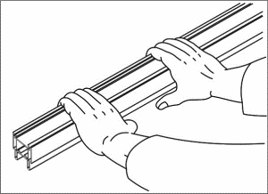
1. Take the workpieces of SF frame.
Turn every workpiece skid rails down
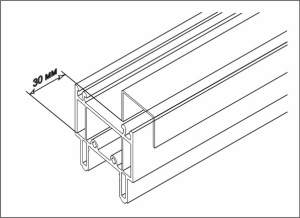
2. Insert reinforcement element into the workpiece.
The reinforcement element should go into the workpiece not less then 30 mm deep. Use tape measure or wooden pattern for convenience.
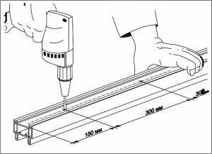
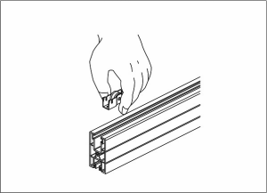
3. Attach the reinforcement element to the workpiece with the screws (B 3,9x16) in increments of 300 mm leaving 150 mm space from each end. Reinforce all the four details the same way.
4. Secure the lower corner pieces to the workpiece with 2 screws (that go in the unit with corner pieces), holding the sealing gasket (to keep it in place). Do the same with the other horizontal workpiece.

5. To avoid moisture seeping into the room it is recommended to intensify water drainage. Round (8 mm) or oblong (6x10mm) orifices are being drilled through the outer “free” (without a fold) rail of the frame. Orifices are being drilled in increments of 400 mm (or less), in compliance with climatic specifics of a region, leaving 5 mm space from filling piece.
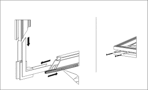
6. Join vertical and horizontal workpieces together with the screws. Lay the construction aflat for convenience.

Frame is ready!
Fold assembly
7. Take horizontal workpieces. Insert rolls into the workpieces leaving 25 mm from the edge, deepening the rolls maximally. Secure with screws if necessary. Drive screws in at low speed.
8. Insert pile weather-stripping into horizontal workpieces. MHR-902 bristles should be placed opposite each other.
9. With a sharp object hook pile weather-stripping by the end and draw along the fold. MHR-902 should overhang the size of the workpiece by 1-2 mm.

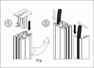
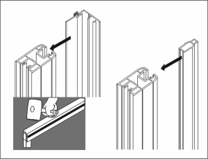
10. Insert frame corner piece and pile weather-stripping into vertical workpiece, insert the second joining element right after.
Repeat the same steps with all the workpieces where pile weather-striping is necessary (see «Fold assembly»).
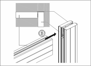
11. Join three workpieces of the fold – two horizontal and one vertical – into U-shaped construction.
12. Gaskets are inserted into inner part of the profile. Gaskets’ number and size depend on the size of the fold. No less than two gaskets are recommended – at the bottom and on each side.
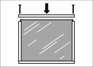
13. Insert glass into U-shaped construction. Fix the fourth workpiece.
14. Insert elastic T-shaped weather strip into horizontal part of the fold. Put it into slot without stretching, slightly compressing only. Cut the end at an angle of 90 degrees and tuck it in a butt joint to the vertical part. Vertical part: cut the edges of rubber at an angle of 60 degrees and roll into the slot the same way as with the horizontal part. Cut the edge at an angle of 60 degrees and tuck it in a butt joint to the horizontal part of the fold. Roll the rubber into the slot of the opposite vertical part the same way. Turn the fold around and install sealing rubber the same way at the other side.

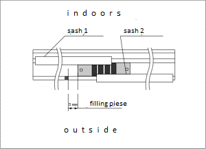
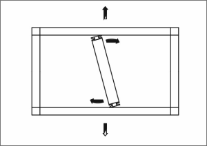
15. Define the element – fold cover or secondary sash (Stulp) – that is used in the fold (as consistent with the picture).
Fold covers and secondary sash (Stulp) installation:
- At the jointing of the folds set on one slide rail: secondary sash imbedded in one piece of a fold, pile weather-stripping – in the other.
- At the jointing of the folds set on different slide rails: fold covers are mounted on both folds without pile weather-stripping.
| L – left (лево) | O – outside (улица) | S – secondary sash (Stulp) (штульп) | PW – pile weather-stripping (ЩУ) |
| R – right (право) | I – indoors (помещение) | C – fold cover (крышка створки) |
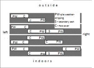
Place fold cover or secondary sash (Stulp) upon vertical part of U-shaped construction previously trimming burred edges. Latch the elements on the vertical part of U-shaped construction. Use a mallet for convenience. Do the same with all the folds.
16. Place the folds the way they will be joined in a frame. Mark the lock position. In case of only one lock it is in the middle. The center of the lock must coincide with the center of the hook placement. Mounting of the lock takes place after the installation of the fold into the frame.

Make sure the folds’ diagonal lines are equal to each other. If their length differs, adjust the length hammering it with a mallet.
Fold is ready!
Window assembly
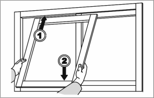
17. Install folds into the frame upper part first and mount folds on rolls. Imbed lock in the fold. First closing takes some effort to put the fold in place.
18. Filling pieces are installed onto frame at the jointing of the folds. Secure filling pieces with screws, maximally moving the folds in turn to the left or right. Afterwards upper filling piece will have to be dismantled to remove the fold.
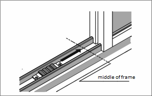
19. Install stoppers. Stoppers are placed on top and bottom parts of the fame where lock and frame may contact.
One stopper can be used if required.

Take protective film off. Window is ready!
Flyscreen assembly
20. Reinforce vertical workpieces of flyscreen (see “Frame assembly”). Reinforcement of the horizontal ones depends on folds’ size.
Insert pile weather-stripping into all the workpieces of flyscreen. Insert joining frame corner pieces into workpiece. Place rolls on the bottom workpiece and secure with screws (B 3.9 х 25 PY) thus joining roll, corner piece and workpiece together at once. Vertical pieces AFF-030 are assembled the same way, without the rolls only. Assemble the rest of the workpieces the same way.
21. Spread the mesh on the fold. Secure the mesh across with the help of gasket driving it in together with the mesh using mallet and adjusting tension. Tension should not be too much because it may lead to deformation of the folds. Cut off the excesses of the mesh.

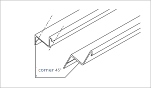
22. Saw the slide rail of the flyscreen off at an angle of 45 degrees.
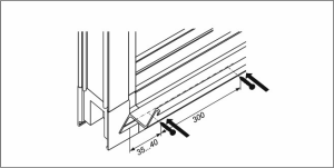
23. Secure four workpieces of sliding rail across the window with drivescrews (4.2х19) in increments of 300 mm leaving 35-40 mm space from the end.
Install flyscreen fold (see “window assembly”, step 1.)
Window with flyscreen is ready!!
Mullion assembly
24. For long constructions (more than 4-4.5 v lengthwise) installation of vertical meeting rail (mullion) is recommended.
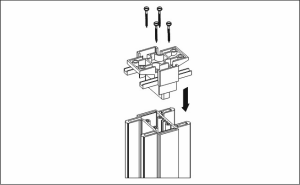
Mullion connectors are inserted into mullion profile and secured with screws.
25. Mullion is installed into assembled but not installed frame and secured to it.
Window with mullion is ready!